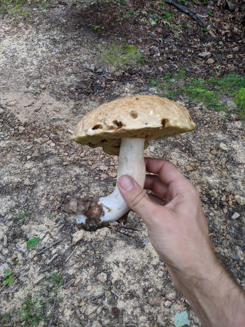
I'm Eli, an engineer and mushroom enthusiast. Here is an accounting of some of my recent projects, trials, and tribulations, and what was learned therefrom.

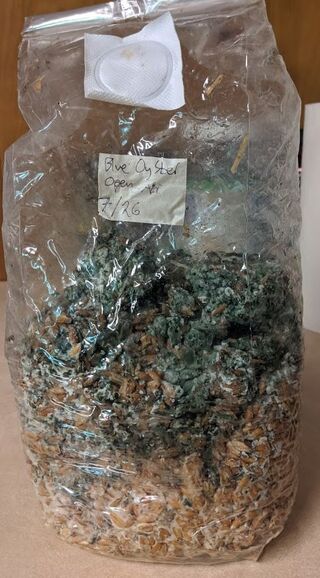 My motivation for this project! A contaminated bag of mushroom grain spawn. Trichoderma mold and likely bacterial bloom. As part of my ambitions for cultivating mushrooms, I needed a far more reliable method of doing sterile work than the old still air box. For those not in the know, a still air box is.... exactly what it sounds like. It's a cheap way to do sterile work (such as transferring cultures to agar plates, grain-to-grain transfers, etc). Most people use clear plastic totes with arm holes cut out. The idea is that an isolated environment in the box with minimally disturbed air will prevent wild spores and microbes from contaminating sterile workpieces, based on the idea that contaminants will only ever fall downwards from the user's hands, or unsterilized equipment. Therefore the basic rule for operating within such a box is to keep your hands and non-sterile tools from being directly above your sterile workpiece (such as an agar plate, open jar of pressure-cooked grain, or whatever else). There's a lot that could go wrong with such a system and few ways to know exactly how your sterile environment was compromised. Furthermore since the tote I had been using as a still air box was only about 16 inches tall it was a huge pain to try and do sterile grain transfers when working with an 18" tall autoclave bag. The main point is I'd been getting increasingly inconsistent results and rising contamination rates. The contamination usually takes the form of green mold on mushroom grain spawn, or bacterial blotches/blooms on agar plates and in liquid culture jars. Since I'm trying to up my game and get more reliable results I decided to build a laminar flow hood, following pretty closely this guide: blog.freshcapmushrooms.com/learn/keeping-it-clean-how-to-design-and-build-a-laminar-flow-hood/ The idea behind a laminar flow hood is, it filters out all airborne contaminants such as mold spores and bacteria so you have a stream of guaranteed sterile air blowing over your work space. A proper clean room or microbiology lab would have positive pressure HEPA filtration in the entire room in addition to such benchtop equipment, but since I'm doing this in a spare bedroom in my house the flow hood is a great place to start. The guide I linked from the FreshCap blog explains the design principles and construction process pretty well so I won't go into much detail here. I decided to go for a 24"x24" HEPA filter because I found one for a good price, and it could accommodate an 18" tall autoclave bag (industry standard for sterilized media in the mushroom growing world) with room to spare. Note that while the FreshCap guide recommends a 99.99% efficient HEPA filter (for 0.3 µm particles), I went with a 99.97%. The slightly less efficient filters are a bit more common and cheaper and I figured 99.97% would be good enough for my purposes. Mold spores are almost all larger than 1.0 µm. I went with a Dayton model 1TDR7 blower because it was the cheapest blower rated for over 400 CFM at a pressure drop of 0.3" water column. That pressure drop is what I estimated as the resistance caused by both the 24"x24" HEPA filter and the prefilter at 400 CFM. My minimum airflow requirement is 380 CFM as that's the volume flow rate equivalent to 100 ft/minute of airspeed coming out of the main HEPA filter. 100 ft/minute is the guideline for good laminar flow in this application, sourced from the guide linked above. I differed from the guide by using 1/2" plywood instead of 3/4", with weight savings in mind. The cost difference really isn't that much, a 4'x8' sheet of 1/2" sanded plywood is only about $10 cheaper than the same of 3/4". For comparison, the blower and HEPA filter together came in at just over $300. 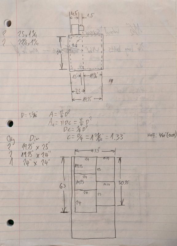 The primary drawing I made to determine dimensions of the cuts I'd make. On top is a side view. Bottom is a plan of how to cut out the 4'x8' plywood sheet for the main box's panels. The equation inbetween was to work out how far the blower's inlet needed to be from the nearest wall for maximum airflow. The drawing on the top half of the sheet above shows a side view of the primary filter housing. You can see that the primary (HEPA) filter is quite deep, 11.75" to be precise. I sized the plenum behind it (where the blower exhausts) so that the internal dimensions of the blower's exhaust duct would not be obstructed. The square of dashed lines in the upper and lower right of the plenum (with the "2x2" callout) indicates a piece of wood there to both provide some extra rigidity to the structure and also stop the HEPA filter from sliding into the plenum area. I ended up making this out of a section of 2"x3" whitewood stud. Initially I fretted about how much space there needed to be between the blower's inlet and the rear panel of the prefilter plenum in order to maintain maximum blower performance (I figured the minimum clearance would be 1.33"). Then I realized I could just rotate it 90 degrees and make it a non-issue. 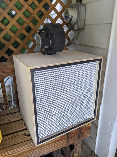 About halfway done by this point. The main box/plenum is complete, with the blower bolted in place. Notice that the blower is actually positioned 90 degrees from where the drawing side view indicated. The blower bolts to the top piece of plywood where I'd cut out a hole with a jigsaw (bought specifically for this project!). Unfortunately, after cutting the hole while smoothing the edges down with a rattail file - I accidentally hit the filter with the end of the file. I couldn't see the back of the filter very well so I figured I'd just bent some of the aluminum fins. Turns out these filters are quite fragile, more on that later. A couple other differences from the FreshCap guide:
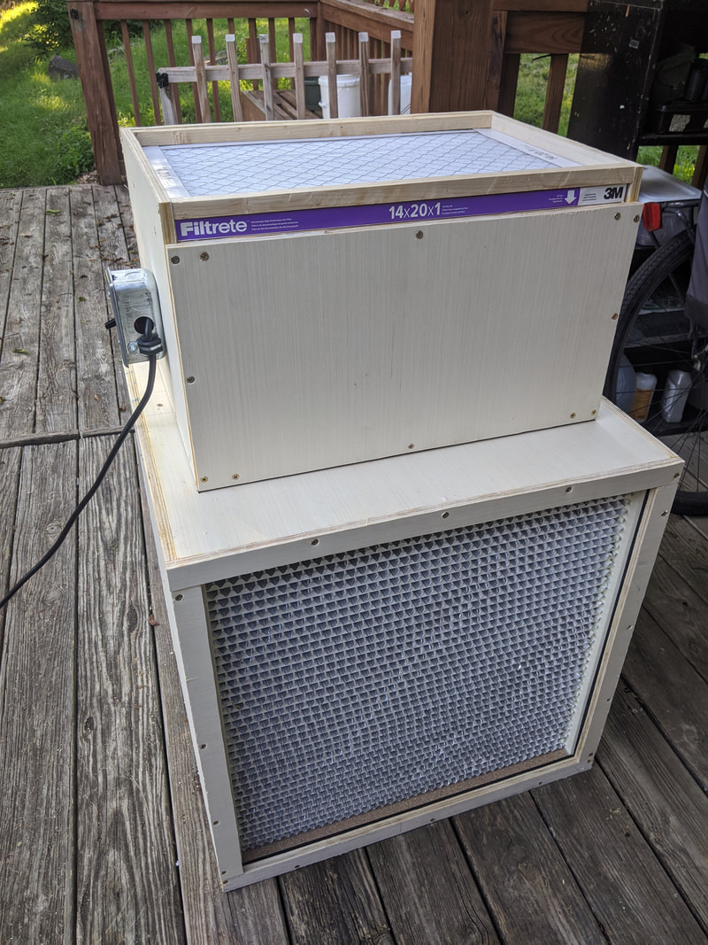
So, having assembled all five panels of the primary filter box, and cut the hole in the top for the blower, I had to get my hands and a wrench on the inside of the plenum to torque the mounting nuts. I did this by removing the rotor from the blower and reaching through the blower. It was rather awkward and took longer than it should have. Order of operations is important when assembling such a machine, so if I ever make another one putting the rear panel on after everything else is done would be more efficient. I used caulk to fill the gaps between the edges of the rear panel and the rest of the box's panels, to make an airtight seal. Wood glue doesn't fill gaps very well and would have made the rear panel nearly impossible to remove. Would also have allowed me to screw the prefilter plenum on from underneath which is easier and more structurally sound that the method I went with in this build. 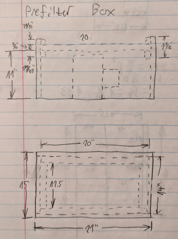 Side view of the prefilter box is on the upper half of the drawing. Top view on lower. 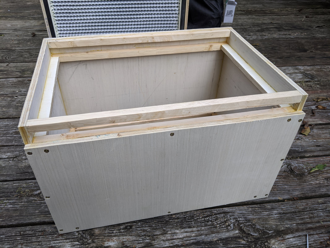 The prefilter plenum assembled, filter slot on top. The prefilter plenum is designed to accept a 20"x14"x1" HVAC filter. The dimensions were chosen based on the particular filter I was able to find at Lowe's. the 20"x14" was a good compromise between flow resistance (more area, lower pressure drop) and size - didn't want the prefilter box to be too huge, in order to save on weight and materials. The 20"x14" filter gives slightly more than 0.1" WC pressure drop at around 400 CFM, which is acceptable. It's constructed using the same techniques as the main filter box. I applied wood glue to the edges and used #8 wood screws with pre-drilled holes to clamp the wood together. The small square sections you can see forming the filter slot is actually reclaimed wood. I saved several slats from a box spring (for a bed) I'd busted up when moving out of my old place a few months ago. I ripped them in half with the jigsaw and then used a hand planer to shave the wavy cut down to a nice straight edge. More of the same battens were affixed to the bottom of the prefilter plenum. The idea is I would attach the plenum to the main filter box by screwing through the battens. That would provide enough clamping force to compress the weather stripping, forming an airtight seal. The alternative to this would have been screwing directly into the plywood edge of the prefilter plenum from below, but that would have required access to the inside of the primary filter box, which I didn't have as explained earlier. The benefit to having the screws accessible from above, however, is that it's easier to remove the prefilter plenum if maintenance needed to be done. 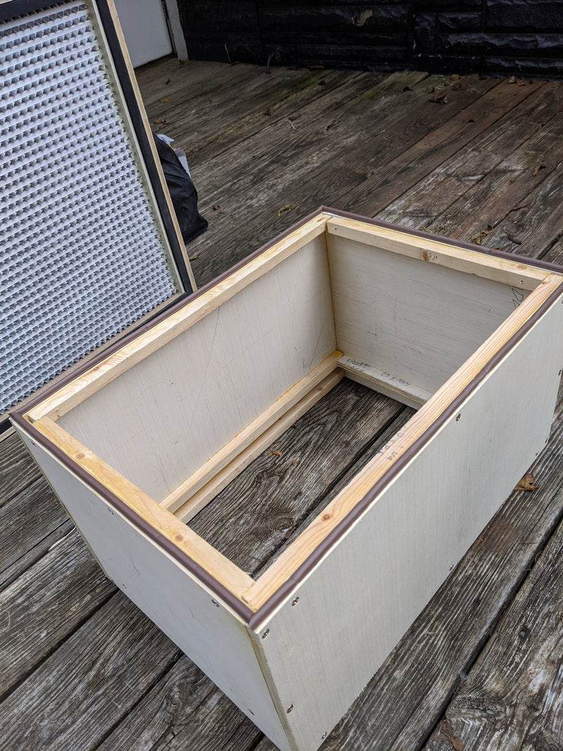 Underside of the prefilter plenum, where it would attach to the top panel of the primary filter box. The dark brown is some foam weather stripping to ensure an airtight seal. The completed flow hood! Well, almost completed... After the prefilter plenum was screwed down I wired the blower to the switch on the lefthand side of the prefilter. Was quite easy to do, drilled a 3/8" hole through the plywood for the wires and pushed some caulk in to deny its use for airflow. 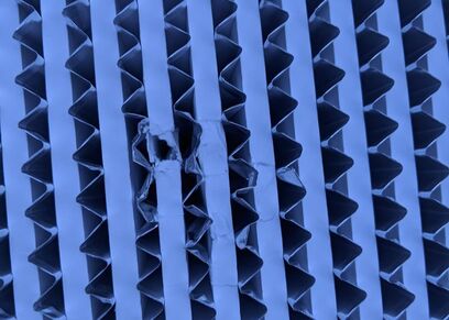 Damage done to the filter by the rat-tail file during assembly. It's a good thing I made the prefilter plenum easy to remove. After assembling all the wooden parts, wiring the blower and switch up, and testing it for the first time, I found out that when I'd earlier smoothed off the edges of the blower hole with a rat-tail file, I'd accidentally punctured the filter membrane of the HEPA. Oops! I had to take the prefilter plenum off to access the screws holding the back panel in. Then, because I'd already caulked the back panel, had to pry it out with a screwdriver. This was an annoying task and damaged the edges of the plywood slightly. After getting the main filter box open I was able to patch up the HEPA with some pieces of printer paper and caulk. After re-caulking the back panel and testing it again I seemed to have even airflow so I can only hope that the repairs are airtight. It's been a couple weeks now since I've built the laminar flow hood and it's working well. The blower draws about 100 Watts, so leaving it on for 10 hours straight to scrub the air of my lab only costs $0.10 in electricity - not bad. Have done 7 or 8 grain transfers infront of the hood and only had one contaminate so far. That's an improvement. My next step is to construct an attachment to the front of the flow hood - an open-ended box - to create a hard barrier between the clean sterile airflow and the rest of the lab in which I can perform sterile work with a high degree of confidence. I will also include a germicidal UV lamp in the attachment box's ceiling that will be turned on to thoroughly sterilize the front of the HEPA filter, the walls of the box, and tools that I leave inside the box. More on that in Part II. Thanks for reading! 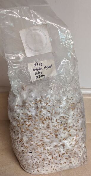 One of the spawn bags produced by grain-to-grain transfer in front of the new laminar flow hood. Happy and healthy!
8 Comments
12/19/2022 09:47:02 am
İnstagram takipçi satın almak istiyorsan tıkla. 1/4/2023 12:31:48 pm
100 tl deneme bonusu veren siteleri öğrenmek istiyorsan tıkla.
Henry
12/15/2023 12:49:04 pm
Thanks, this was usefull! Leave a Reply. |
Eli MeyerEngineer and extreme DIY enthusiast. ArchivesCategories |
 RSS Feed
